L1.1: Camera calibration
Calibration of monocular camera in different scenarios.Camera calibration basics
Camera is the most important piece of hardware in computer vision. To be able to extract as much useful information as possible from the images gathered, some camera parameters are required.
Pinhole camera model and image projection
On the picture below you can see the simple, pinhole camera model. A real-world point P=(X,Y,Z) is seen by the camera at the coordinates (u,v) on the image plane. Those coordinates depend on the focal length f from the camera origin to the camera sensor and the coordinates of the principal point (cx, cy), i.e. the optical center of the sensor.
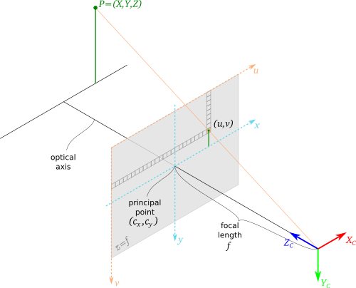
First goal of the calibration is to estimate those parameters.
Optical distortions
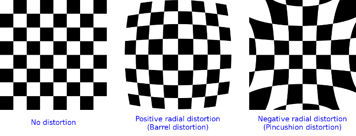
As the real cameras are not perfect, especially when it comes to optics, acquired image is almost always distorted in some way. Lens imperfections and optical phenomena can result in many different distortion types, out of which two main types can be distinguished - radial and tangential
Radial distortions can be of two types. Barell distortion effects in image corners squeezed towards the image center. Pincushion (or pillow) distortion is the opposite - corners are pushed away from the center.
The tangential distortion corrects for tilts of the image plane after radial distortion. It is caused by the subtle manufacturing flaws where the optical elements not aligned with the imaging plane.
During the calibration process, distortion coefficients can be estimated, and after that image can be restored to ideal, straight form.
Calibration process overview
To estimate camera parameters mentioned before, the calibration procedure can be used. As the input to the optimization procedure a set of 3D points (from the world) and a set of their 2D projections (on the image) must be provided. There should be enough points for the optimization procedure to run, and all the image parts should be covered. It is also important to cover different distances from the camera.
In general, however, this process is very hard (it is hard to tell what are the real 3D coordinates of the points in the world). For that reason, different procedure is widely adopted for the camera calibration. Instead of giving points with the known position, a pattern of known size is used. Then, during the calibration procedure, point coordinates in the pattern reference frame are given along with their projections in the picture. In this scenario, apart from the camera parameters, also the pattern poses in the world are estimated, which requires even more points to be provided.
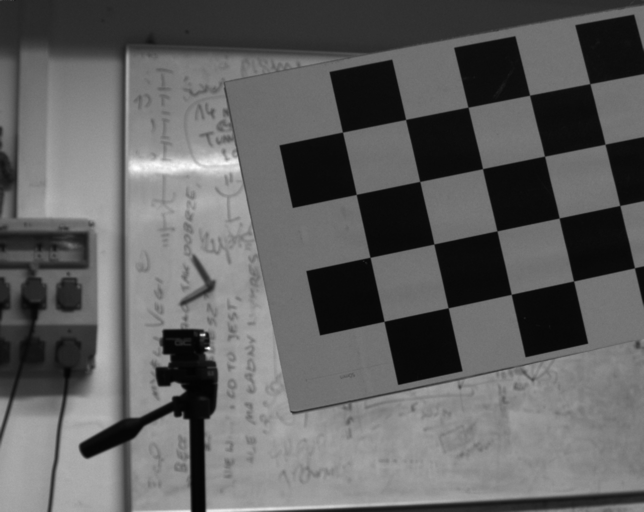
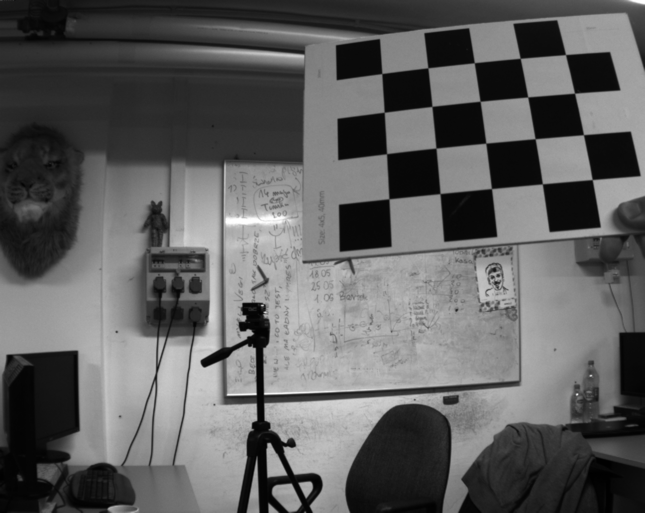
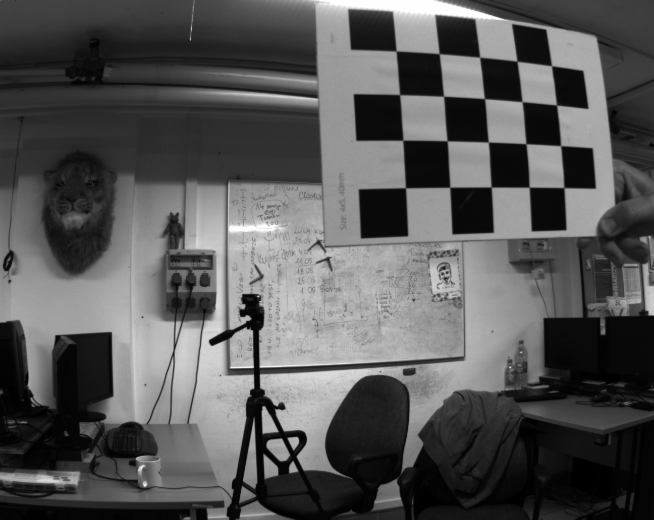
Chessboard calibration pattern is the most popular one - it is easy to detect in the image and it provides a lot of points from the single detection. For that reason, in the following task, you will use chessbord patterns to calibrate the camera using the Matlab Computer Vision Toolbox.
Running calibrator app
In Matlab, open the Apps tab and select Camera Calibrator.
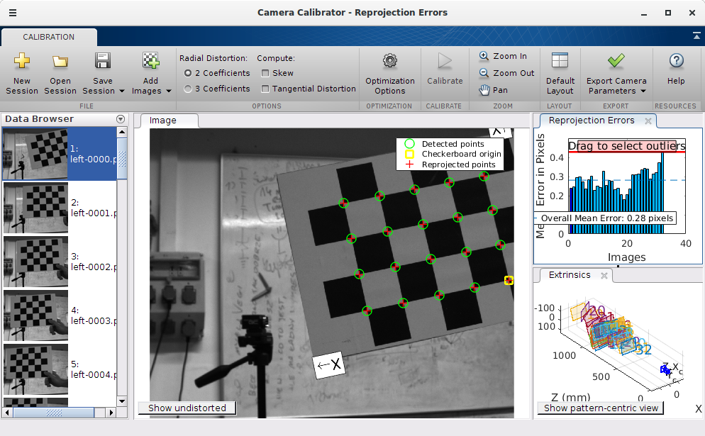
Load the calibration images and perform calibration for different combinations of parameters (2/3 coefficients, skew and tangential distortion). After calibration analyze the results (reprojection errors) and observe difference between original and undistorted pictures.
Look at the final intrinsic parameters (export camera params) and compare results (mainly focal length and image center) for different lens settings. Work with three data sets:
| Narrow angle | Medium angle | Wide angle |
|---|---|---|
 |
 |
 |
| calib_narrow | cailb_medium | calib_wide |
For more detailed information refer to Matlab documentation.